The technical resources below are here to help with any questions you may have. If you are not able to find what you are looking for or need help, Midland Technologies is happy to assist you. You can contact us at (763) 428-4229 or by email at info@lethiguelusa.com.
FAQs
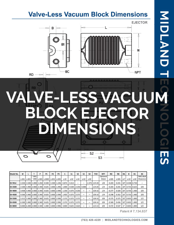
Midland Valve-Less Vacuum and Vent Blocks have been designed with a tooth gap found to be most effective for a broad range of casting processes. We are able to provide blocks with larger tooth gaps upon request. We recommend filling out our Valve-Less Vacuum/Vent Block Sizing form (or download) so that we may provide a recommendation on needed evacuation area. Our technicians can then work with you to determine the optimal tooth gap to block size ratio for your process.
The air and gas present in a die cavity, runner system, and shot sleeve in the case of a cold chamber machine, must be evacuated by some means. These include conventional venting, vent blocks, or vacuum-assist. If gas is not evacuated sufficiently, part quality can be degraded, both in terms of function and cosmetics.
Vacuum-assist provide a positive pull to evacuate the largest volume of air and gas in the shortest amount of time from the die cavity. This can help to reduce scrap, and to cast more complex shapes. Not all dies require vacuum to achieve low porosity levels that meet customer specifications. In these cases, a vent block can provide the greatest area to achieve air and gas evacuation.
It is true that not all dies require vacuum to achieve low porosity levels that meet customer specifications. In these cases, a vent block can provide the greatest area to achieve air and gas evacuation while helping to reduce excess material loss.
Yes, we calculate the needed evacuation area as a function of fill time to volume. In order to do this we utilize PQ2 and proprietary calculations developed internally and proved out over years of real life applications. Note that vacuum-assist requires a smaller area in relationship to venting than either conventional venting or vent blocks due to the positive pull that it provides.
We calculate the required vacuum or venting area based on a number of factors related to the die casting machine capabilities, casting volume, cavity fill time, slow shot time, and gate area.
By submitting a completed Valve-Less Vacuum/Vent Block Sizing form (or download) provided by Midland Technologies to be used in calculating the required area for a specific tool.
If we receive a completed information sheet in the morning, we can often have the results the same day.
Troubleshooting
Poor cavity fill can result from a variety of process and engineering factors. In the case of vacuum-assist die casting, poor cavity fill and/or continued porosity can result when there exists a blockage or failure to achieve open flow path between the cavity and the vacuum tank. The below possible causes and solutions are representative of issues that can cause a reduction or elimination of the efficacy of the vacuum-assist method in the casting process.
It is recommended to first ascertain the level of vacuum being achieved in the die cavity for reference. This can be done by placing a rubber mat over the pour hole while the die is in the closed condition. Slit the rubber mat and place a vacuum gauge within the slit. Turn the vacuum pump on, ensure the tank is at vacuum pressure, and activate the system by opening the solenoid. Check the vacuum gauge at the pour hole to determine if an effective vacuum level has been obtained through the cavity.
Cause:
Plugged Vacuum Block
Solution:
Metal solder and lubricants can build up in the serrated tooth pattern over time according to process variables and alloy being cast. This can reduce the effective flow air for air to evacuate through the block. The best solution is to setup a regular maintenance schedule where the blocks are cleaned with a brass brush once or more per shift.
Cause:
Plugged Filter
Solution:
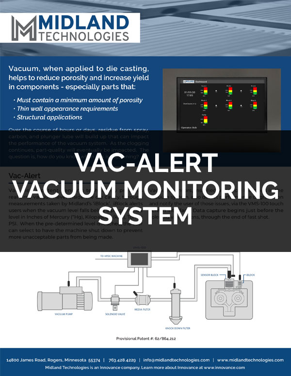
Filters on the vacuum system will require regular cleaning. The frequency depends upon the specific casting process and alloys being cast. Filters can be monitored for indication of blockage by placing a vacuum gauge before and after the filters on the system. Any differential between the gauge readings on the pump side and on the die press side may indicate a need to check the filters. Midland FL-0016 Media Filters have quick-connect ends for easy change out when one become clogged. Midland-FL-0803 Knockdown Filters have removable baffles for easy cleaning, and a ball valve to quickly drain any trapped liquid.
Cause:
Pinched or Punctured Vacuum Hose
Solution:
It is critical to system integrity that the vacuum hoses and connections be checked periodically for blockage, restriction, and/or punctures. These can all reduce the free flow of air from the cavity to the vacuum tank.
Cause:
Excessive Die Leakage
Solution:
It is possible, that there exists so much air leakage into the die cavity, that the vacuum system is unable to sufficiently evacuate the air in the cavity, or the Valve-Less Blocks do not provide sufficient area to allow full air evacuation in the allotted time. Vacuum systems and Valve-Less Blocks are sized based on calculations which take into account the volume of air that must be evacuated, and the time in which that air must be evacuated to allow for cavity fill. While safety factors are built in to the calculation, changes to process and/or die press may result in air leakage that over comes the vacuum system and/or Valve-Less Blocks. In this case the process engineer or operator must assess variables such as die alignment, fill times, and whether the die is properly held closed during injection.
Cause:
Misalignment of Vacuum Block(s)
Solution:
If blocks are not aligned properly it will restrict the effective flow area through which air from the cavity and system passes. Check the alignment of Valve-Less Vacuum Blocks by placing a piece of lead solder on the serrated part of the block and then closing the die. Next, measure the cross sections of the vertical angles of each serration using a caliper. The critical factor is to ensure that the thickness of each vertical angle corresponds to its opposite vertical angle for each serration.
If the measurements of the thickness of two opposite angles differ greatly, it indicates misalignment of the stationary and ejector side halves. Misalignment can reduce or completely choke off the air flow through the blocks. It will be critical to ensure that blocks are properly installed using the pucks on the back sides as reference edges.
Flashing around Valve-Less Vacuum Blocks or Valve-Less Vent Blocks can buildup which holds the die open and compromises the efficacy of vacuum-assist or massive venting. This in turn can lead to continued porosity issues. It is critical to clean any flash from around Valve-Less Blocks.
Cause:
Gap Between Valve-Less Block and Cavity or Runner Insert
Solution:
Ensure that the Valve-Less Blocks are correctly installed and that there is no gap or height difference between the block and runner or cavity insert.
Cause:
Die Holding Open
Solution:
If the die is not being held completely closed during the injection phase, this can lead to the stationary and ejector halves of the Valve-Less Vacuum or Vent Block also failing to close completely. The result can be flash as metal is not fully contained within the block runners and block flow pattern. In this case the die and/or press alignment is the issue and must be addressed accordingly.
Cause:
Excessive Metal Velocity
Solution:
If metal exits the runners from the cavity to the Valve-Less Block with excessive velocity, it can result in flash around the blocks as metal is not contained within the runners and flow pattern. Midland recommends a minimum of five 90 degree turns in the vacuum or vent runners before reaching the inlet of the Valve-Less Block(s).
If the vacuum pump is not achieving the expected level of vacuum within the receiver tank, check to ensure that all drain valves are closed. If all drain valves are closed, then check the oil level, oil quality and all filters on pump. Replace the oil and filters as needed. If this does not resolve the issue, please contact us for further technical assistance. Pumps should be overhauled periodically. Overhaul and filter kits can be purchased directly from Midland Technologies. Please have your pump model number ready when contacting us.
If the vacuum pump is not achieving expected vacuum levels in the die cavity, see the section above on troubleshooting Poor Cavity Fill as these are similar issues. We recommend placing vacuum gauges on either side of the filters in the system to monitor vacuum levels on the die cast machine side of the solenoid. You may also put a t-pipe at the vacuum block(s) and connect a gauge to monitor vacuum at the block when the solenoid is open.
Note that significant die leakage can introduce enough air to overcome the ability of the vacuum pump to achieve expected vacuum levels. For this reason it is critical to evaluate vacuum levels within the cavity by using the method of covering the pour hole described in the Poor Cavity Fill troubleshooting section above.
If metal fines are filling the vacuum hose connected to the Valve-Less Vacuum Blocks or reaching farther into the vacuum system, you may need to install a filter closer to the block. This will require regular cleaning of the filter so as to maintain a free outflow of air from the cavity. Alternatively, you can disconnect the hose section and blow it out as needed. Either solution is satisfactory and depends upon the specific casting process.
Systemically metal dust may be caused by velocity of metal entering the chill vent as it “freezes” off. It is possible to reduce this in some cases by reviewing exit runners to ensure proper reduction in velocity.
Cause:
Excessive Metal Velocity
Solution:
If metal exits the runners from the cavity to the Valve-Less Block with excessive velocity, it can washout the steel of the critical flow area and result in sticking. Midland recommends a minimum of five 90 degree turns in the vacuum or vent runners before reaching the inlet of the Valve-Less Block(s). Midland will provide a recommended vacuum block runner layout free of charge for any die using Midland Valve-Less Vacuum Blocks.
Cause:
Damaged Block
Solution:
It is recommended to periodically check the critical flow area of Valve-Less Blocks in order to ensure that there is no damage to the teeth. Pits, nicks, and broken teeth can result in sticking. If the block appears damaged, remove and replace with a new block.
Cause:
Metal Solder
Solution:
In the event that metal is soldering to the Valve-Less Blocks, it is recommend that the cooling lines be utilized and/or release agent be sprayed on the area that is sticking.
Cause:
Excessive Metal Velocity
Solution:
If metal exits the runners from the cavity to the Valve-Less Block with excessive velocity, it can washout the steel of the critical flow area and result in sticking. Midland recommends a minimum of five 90 degree turns in the vacuum or vent runners before reaching the inlet of the Valve-Less Block(s). Midland will provide a recommended vacuum block runner layout free of charge for any die using Midland Valve-Less Vacuum Blocks.
Cause:
Damaged Block
Solution:
It is recommended to periodically check the critical flow area of Valve-Less Blocks in order to ensure that there is no damage to the teeth. Pits, nicks, and broken teeth can result in sticking. If the block appears damaged, remove and replace with a new block.

CUSTOM DESIGN OPTIONS
Whether you need a replacement block or a new unique block for your project, Midland is your
solution source for any of your custom needs.
Custom designs and alternative formats include: Custom Dimensions, Corner Radii, Double
Flow Areas, Ejection Pin Holes, Custom Water Lines and Steps.

